THE SAN FERNANDO AUTOMATIC MERIDIAN CIRCLE
IN SAN JUAN
Mui�os, J.L., Beliz�n, F., Vallejo, M.
Real Instituto y Observatorio de la Armada,
Plaza de las Marinas s/n,
11110 San Fernando,
Spain
ppmu@roa.es, belizon@roa.es, vallejo@roa.es
Mallamaci, C., P�rez, J.A.
Observatorio Astron�mico F�lix Aguilar,
Avda. Benav�dez 8157 oeste,
5407 Marquesado,
San Juan,
Argentina
ccmalla@unsj.edu.ar, joeperez@arnet.com.ar
ABSTRACT
The meridian circle of the Real Instituto y Observatorio de la Armada en San
Fernando (ROA) was built in 1948 by Grubb-Parsons. In 1987 the observations
were stopped and began a process of complete automation of the observations
in a similar way as it twin telescope the Carlsberg Automatic Meridian
Circle (CAMC). In 1996 after a period of test observations in San Fernando
was moved to Argentina, to the Carlos U. Cesco (CUC) observatory of the
Observatorio Astron�mico F�lix Aguilar (OAFA) of San Juan University where
is operate jointly by the ROA and the OAFA. The CUC is placed in the west of
Argentina near the Andes at 31� South, 69� West and 2330 m over the sea
level. Since 1996 August to 1999 November the observations were carried out
with an scan slits micrometer. On 1999 December an Spectrasource CCD camera
of 1552x1024 pixels of 9 ( , borrowed by the Copenhague University
Obsevatory, was installed in the instrument. The CCD camera observes in
drift scan mode. Since then a survey of the South sky from 0� to -60� is
been observed. Maximun priority is given to the zone -3� to -9� the same
zone observed in San Fernando for the Astrophotographic Catalogue in order
to computes proper motions using new measures of the AC plates.
1 THE INSTRUMENT
The C�rculo Meridiano Autom�tico de San Fernando (CMASF) is a meridian
telescope with 2664 mm of focal length. The object glass is an achromatic
doublet with an useful aperture of 176 mm built in 1997 by Ealing. In 1991
the original declination glass circle was changed for a new one built by
Heidenhain, the circle has 724 mm of diameter and is engraved every 5
minutes. Since 1999 December observe with an CCD camera working in drift
scan mode (Gehrels, 1991).
The observations are carried out in a completely automatic mode. The
automation is controlled by a PC, the telescope controller computer (TCC).
The synchronization is provided by a GPS receptor and a timing an
synchronization card Odetic installed in the TCC bus. The GPS card supply
time to the microsecond and a 10 KHz frequency pulse. This frequency is
converted in a TTL pulse of 1 KHz sidereal by a microcontroller card. The
sidereal KHz is the time base to implement the sidereal time that
synchronize all the automation and the observations.
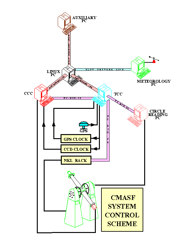
Another PC, the camera control computer (CCC), control the camera and a
third one collect and record the data from the meteorological sensors the
MDC. All three PC's are interconnected via a LAN served by a fourth PC
running in linux, this disposition will be able the CMASF remote control
when the CUC telephonic system will be connected to Internet. In the figure
1 is showed an scheme of the CMASF complete system.

The CMASF automation is divided in several subsystems, they are mainly:
1.1 The setting
The setting of the telescope works in two steps. In the first one, slew
motion, after release the brake a couple of torque motors rotate the tube
until set it in a position very near to the required, the rotated angle is
measured by a incremental encoder.
Once reached that position the tube is braked and the fine motion began, an
stepping motor acting on the brake arm move slightly the tube until the
final position. While the fine motion is working the circle reading system
is measuring the position of the circle in order to assure that the tube is
setting in the right position. The setting take a maximum of 40 seconds with
a precision better than 5 arcseconds.
1.2 The circle reading system
As was mentioned former, the declination circle is a glass circle engraved
every 5'. The circle position is measured by six microscopes 60� apart one
of the other. Every microscope is provided with a CCD CCTV camera, the image
of the focal plane of every microscope is sequentially read by other PC (the
CRC) via a frame-grabber card and then a digital image processing program
compute the circle position with a precision of about 3 hundredth of arc
seconds in less than two seconds.
1.3 The CCD camera
Is an Spectrasource camera with a Kodak 1600 CCD sensor of 1532x1024 pixels
of 9 (, having in account the scale of the object glass a region of sky of
18'x12' is covered by the sensor. The camera works in drift scan mode, in
this way an strip of sky of 18' in declination and until one hour in right
ascension is scanned. It is controlled by a PC that communicate with the
other PC's via the local network, in its hard disc are recorded temporally
the files with the observed scans. A microcontroller card synchronized with
a 10 KHz GPS frequency supply the reading rate to the camera. The transit of
a celestial body through the CCD sensible surface take about 48 seconds in
the equator.
2 OBSERVATIONAL PROGRAM
Since end of 1999 December the CMASF is observing a survey of the south
hemisphere until -60�. The maior priority is given to the zone -3� t0 -9�
because this was the zone observed by the ROA Gautier astrographe in the
"Carte du Ciel" project and there is running a joint project with the CIDA
of M�rida (Venezuela) in order to remeasure the astrographic plates observed
in San Fernando at the beginning of the XX century with a microdensitometer
machine and, simultaneously, reobserve the zone with the CMASF in Argentina
and the CCD mosaic astrographe of the CIDA. In this way it will be possible
to compute good proper motions for the stars of that zone.
3 RESULTS
The results of the first six month of observation are highly encouraging,
the standard deviations in right ascension and declination of two
observation of the same scan are about 0".10 until 14 magnitudes, so we will
expect one mean error of a final position in the range of 0".06.
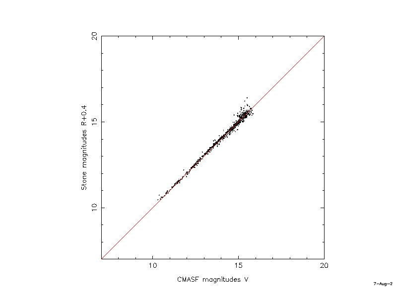
 In figure 2 are showed the magnitudes of the stars in one scan versus
Stone's calibration zones magnitudes+ 0.4 (Stone, 1999), we add 0.4
magnitudes to Stone's values because this magnitudes are in the R band and
the CMASF are computed in the V band.
REFERENCES
Gerhel, T. Sp. Sci. Rev. 58: 347-375,1991
Stone, R.C., Pier, J.R. and Monet, D.G., Astron. J., 118: 2488-2502, 1999
Postscript versions (1,
2) of above plots.


